|
- Front:
- The end of the key nearest the operator when the key is
being used
- Rear:
- The end of the key furthest from the operator when the key
is being used
- Left:
- The side of the key to the operators left when operating
the key
- Right:
- The side of the key to the operators right when operating
the key
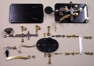
- Base:
- The thin, flat, rectangular (3" x 4 3/4") Bakelite slab to
which the Frame is attached
- Frame:
- The heavy, oval shaped metal support for the main parts of
the key, including the Lever and Trunnion
- Lever and Trunnion:
- The flat, cross-shaped steel piece which is moved up and
down using the Operating Knob
- Lever:
- The longer piece of the Lever and Trunnion
- Trunnion:
- The shorter cross piece on the Lever and Trunnion
- Operating Knob:
- The Knob or Button used to operate the key to send code
- Hammer:
- The upper electrical contact, attached to the bottom of
the Lever
- Anvil:
- The lower electrical contact, attached to the top of
the Frame
- Anvil Strap:
- "L" shaped thin metal strap connecting the Left Inner Binding
post to the Anvil. (The Left Inner Binding Post, the Anvil
Strap, and the Anvil are insulated from the rest of the key)
- Circuit Closing Switch:
- The thin, movable, "S" shaped metal strap attached to the rear of
the frame and extending forward to the right of the Anvil Strap
- Circuit Closing Switch Knob:
- The small knob next to the Operating Knob used to move the
Circuit Closing Switch
- Knurling:
- A series of small ridges along the edges of various screws and
nuts used to connect and adjust the key. The patterns of these ridges
sometimes provide
evidence for identifying the type or manufacturer of a key.
- Thumb Screw:
- A screw with a knurled head, allowing it to be tightened/loosened
by hand. There are 8 Thumb Screws: 4 are Adjusting Screws and 4
are Binding Post Screws.
- Adjusting Screw:
- A Thumb Screw used to change the position or operation of parts
of the key
- Gap Adjusting Screw:
- The Adjusting Screw threaded into the Rear of the Lever
- Tension Adjusting Screw:
- The Adjusting Screw threaded into the Lever near the Main
Knob, which is used to adjust the Spring tension
- Trunnion Screws:
- Two Adjusting Screws, one threaded into the support on each
side of the frame, which hold, and provide a pivot for, the
Trunnion
- Lock Nuts:
- Knurled nut on an each Adjusting Screw shaft, between the head
of the screw and the piece into
which the screw is threaded. There is a Lock Nut on the Gap Adjusting
Screw, Tension Screw, and each of the two Trunnion Screws
- Binding Post:
- A device used to hold, and make contact with, an electric wire.
There are 4 Binding Posts: 2 Inner Binding Posts and 2 Rear
Binding Posts
- Binding Post Screw:
- A Thumb Screw threaded into the top of a Binding Post
- Inner Binding Posts:
- The two Binding Posts on the Rear of the Frame
- Rear Binding Posts:
- The two Binding Posts nearest the Rear edge of the Base
- Binding Post Positioning Pins:
- Wire pins inserted into the bottom of a Binding Post to
prevent it from turning. All J-38's have positioning pins in the
Rear Binding Posts. Lionel J-38's also have positioning pins in
the Inner Binding Posts.
- Rear Shorting Strap:
- Thin metal strap connecting the Rear Binding Posts to
each other
- Spring:
- Coil spring between the Frame and the Tension Screw
- Spring Holder:
- An indentation in the frame or a small metal lip attached
to the frame to hold the bottom of the spring
Two Lionel J-38 keys
|
|